
The building model is calculated in two phases:
- Global 3D calculation of the global model, where the slabs are modeled as a rigid plane (diaphragm) or as a bending plate
- Local 2D calculation of the individual floors
After the calculation, the results of the columns and walls from the 3D calculation and the results of the slabs from the 2D calculation are combined in a single model. This means that there is no need to switch between the 3D model and the individual 2D models of the slabs. The user only works with one model, saves valuable time, and avoids possible errors in the manual data exchange between the 3D model and the individual 2D ceiling models.
The vertical surfaces in the model can be divided into shear walls and opening lintels. The program automatically generates internal result members from these wall objects, so they can be designed as members according to any standard in the Concrete Design add-on.

In the Concrete Design provides an option to perform seismic design according to AISC 341-16 for steel members.
Five SFRS types (Seismic Force-Resisting Systems) are available for this.
More Information
The modal relevance factor (MRF) can help you to assess to which extent specific elements participate in a specific mode shape. The calculation is based on the relative elastic deformation energy of each individual member.
The MRF can be used to distinguish between local and global mode shapes. If multiple individual members show significant MRF (for example, > 20%), the instability of the entire structure or a substructure is very likely. On the other hand, if the sum of all MRFs for an eigenmode is around 100%, a local stability phenomenon (for example, buckling of a single bar) can be expected.
Furthermore, the MRF can be used to determine critical loads and equivalent buckling lengths of certain members (for example, for stability design). Mode shapes for which a specific member has small MRF values (for example, < 20%) can be neglected in this context.
The MRF is displayed by mode shape in the result table under Stability Analysis → Results by Members → Effective Lengths and Critical Loads.

With the Concrete Design add-on, you can perform the fatigue design of members and surfaces according to EN 1992‑1‑1, Chapter 6.8.
For the fatigue design, you can optionally select two methods or design levels in the design configurations:
- Design Level 1: Simplified design according to 6.8.6 and 6.8.7(2): The simplified design is performed for frequent action combinations according to EN 1992‑1‑1, Chapter 6.8.6 (2), and EN 1990, Eq. (6.15b) with the traffic loads relevant in the serviceability state. A maximum stress range according to 6.8.6 is designed for the reinforcing steel. The concrete compressive stress is determined by means of the upper and lower allowable stress according to 6.8.7(2).
- Design Level 2: Design of damage equivalent stress acc. to 6.8.5 and 6.8.7(1) (simplified fatigue design): The design using damage equivalent stress ranges is performed for the fatigue combination according to EN 1992‑1‑1, Chapter 6.8.3, Eq. (6.69) with the specifically defined cyclic action Qfat.

The Concrete Design add-on allows you to perform the seismic design of reinforced concrete members according to EC 8. This includes, among other things, the following functionalities:
- Seismic design configurations
- Differentiation of the ductility classes DCL, DCM, DCH
- Option to transfer the behavior factor from a dynamic analysis
- Check of the limit value for the behavior factor
- Capacity design checks of "Strong column - weak beam"
- Detailing and particular rules for curvature ductility factor
- Detailing and particular rules for local ductility

Would you like to calculate curved beams (for example, made of glued-laminated timber)? For this purpose, you can use various section distributions for members:
- Curved
- Pitched cambered beam with constant height
- Pitched cambered beam with variable height
- Fish beam | Parabolic

When designing connections, you can now also insert a new member as a component directly in the Steel Joints add-on. This will only be considered for the connection design. You can use the Weld and Fasteners components to connect to other members.
Furthermore, it is possible to use the Member Section and Member Editor components and arrange reinforcement elements on the inserted member, such as stiffeners and tapers.
Go to Explanatory Video
Lines can be imported into RFEM either as lines or members. The names of layers are adopted as the cross-section names, and the first material from the predefined materials is assigned. However, if the section of the Dlubal cross-section library and the material are recognized from the layer name, they are adopted as well.

In the Steel Joints add-on, you can determine the initial stiffness Sj,ini according to Eurocode and AISC. This can be done for selected members with reference to the internal forces N, My, and Mz.
In the Members tab of the input dialog box of the Steel Joints add-on, you can select the desired internal forces via a checkbox. Multiple selection is possible. For these internal forces, the stiffness analysis is carried out with a positive and a negative sign.
Go to Explanatory Video
In RFEM and RSTAB, you can design members with the "Laminated Veneer Lumber" material type. The following manufacturers are available:
- Pollmeier (Baubuche)
- Metsä (Kerto LVL)
- STEICO
- Stora Enso
In the ultimate configuration, you can consider strength coefficients for increasing the strengths. The coefficients reducing the strengths are automatically taken into account regardless of this. Try it now!
Go to Explanatory Video
The design of cold-formed steel members according to the AISI S100-16 / CSA S136-16 is available in RFEM 6. Design can be accessed by selecting “AISC 360” or “CSA S16” as the standard in the Steel Design Add-on. “AISI S100” or “CSA S136” is then automatically selected for the cold-formed design.
RFEM applies the Direct Strength Method (DSM) to calculate the elastic buckling load of the member. The Direct Strength Method offers two types of solutions, numerical (Finite Strip Method) and analytical (Specification). The FSM signature curve and buckling shapes can be viewed under Sections.

In the Steel Joint add-on, you can design the connections of members with composite cross-sections. Furthermore, you can perform joint design checks for almost all thin-walled cross-sections in the RFEM library.
Go to Explanatory Video
In the Timber Design add-on for RFEM, you can design members as well as surfaces according to Eurocode 5, SIA 265 (Swiss standard), CSA O86 (Canadian standard), or ANSI/AWC NDS (American standard); for example, cross-laminated timber, glued-laminated timber, softwood, mass timber, and so on.
Go to Explanatory Video
Utilize this time-saving step! This feature allows you to define or edit the member reinforcement for several members or member sets at the same time.
Go to Explanatory Video
Would you like to perform cross-section design checks for cold-formed steel members according to EN 1993‑1‑3? No matter if you design the cold-formed sections from the cross-section library or the general cold-formed (non-perforated) sections from RSECTION – your structural analysis program helps you to determine the effective cross-section, taking into account the local buckling and instability. You can also perform a cross-section check according to EN 1993‑1‑3, 6.1.6. In this case, the internal forces from the calculation using Torsional Warping (7 DOF) are taken into account by means of the equivalent stress check
Go to Explanatory Video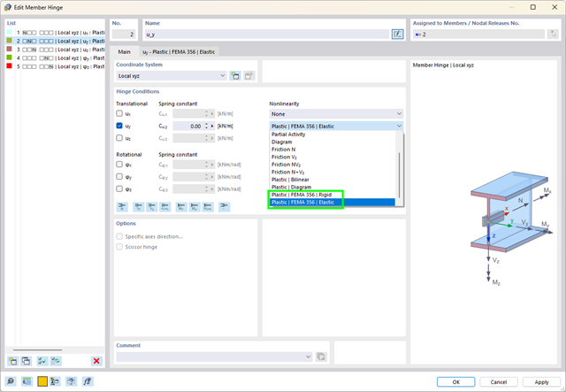
What are plastic hinges? Very simple – plastic hinges according to FEMA 356 help you to create pushover curves. These are nonlinear hinges with preset yield properties and acceptance criteria for steel members (Chapter 5 of FEMA 356).
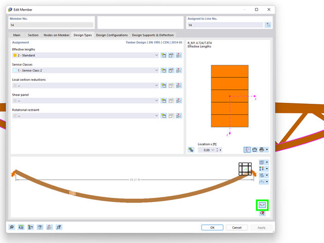
The "Design Types" tab in the member properties allows you to optionally display the real element geometry. Using this feature, you get a clear representation of
- curved beams,
- buckled poly-members, and
- buckled member sets
to define the design properties.
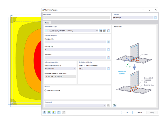
You probably already know that node, line, and surface releases are used to define transfer conditions between objects. For example, you can release members, surfaces, and solids from a line. It is also easily possible for the releases to have nonlinear properties, such as "Fixed if positive n", "Fixed if negative n", and so on.
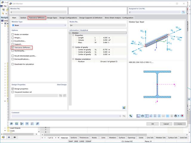
Do you want to generate surfaces from members? Nothing is easier than that. You can find the right solution under Transverse Stiffeners Options when processing the members. In this case, you can adjust the transverse stiffeners according to the type and position.
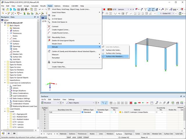
Did you know that you can extrude surfaces into members? In this case, the program assigns a desired member property to the lines generated by the extrusion. A few clicks later, you are already at the desired result.
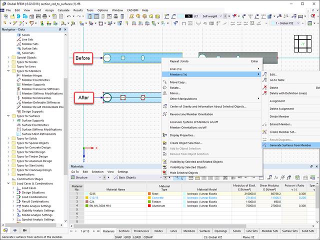
Converting members to surface models works without any major problems. Easily generate member local section reductions using the Generate Surfaces from Members function. Thus, you can convert the members into surface models.
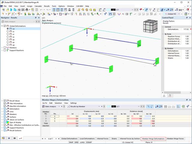
The results for members can be displayed graphically, using the Member Hinges navigator category. The numerical results of member hinges can be found in the Results by Member table category. The Member Hinge Deformations and Member Hinge Forces tables are available for the analysis and documentation of the deformation and force results in the area of member hinges.
The table lists the deformations and forces of each member for the locations specified in the Results Table Manager. There, you can also control which extreme values are displayed.

You can find the serviceability limit state design checks in the result tables of the Aluminum Design add-on. They are already fully integrated there. You have the option to display the design results with all the details at each location of the designed members. You can also use graphics with the result diagrams of the design ratios.
You can integrate all result tables and graphics into the global printout report of RFEM/RSTAB as a part of the aluminum design results. RFEM/RSTAB also allows you to display and document the deformations of the entire structure independently of the add-on.
Was your design successful? Very good, now comes the relaxed part. Because the program gives you the performed design checks in a table. You can display all result details in detail here. The clearly presented design formulas ensure that you will be able to understand the results without any problems. There is no black-box effect with Dlubal Software.
The design checks are carried out at all governing locations of the members and displayed graphically as a result diagram. You can find more detailed graphics in the result output. This includes the stress distribution on the cross-section or the governing mode shape, for example.
All input and result data are part of the RFEM/RSTAB printout report. You can select the report contents and extent specifically for the individual design checks.

In the "Deflection and Design Support" tab under "Edit Member", the members can be clearly segmented using optimized input windows. Depending on the supports, the deformation limits for cantilever beams or single-span beams are used automatically.
By defining the design support in the corresponding direction at the member start, member end, and intermediate nodes, the program automatically recognizes the segments and segment lengths to which the allowable deformation is related. It also automatically detects whether it is a beam or a cantilever due to the defined design supports. The manual assignment, as in the previous versions (RFEM 5), is no longer necessary.
The "User-Defined Lengths" option allows you to modify the reference lengths in the table. The corresponding segment length is always used by default. If the reference length deviates from the segment length (for example, in the case of curved members), it can be adjusted.

When defining the input data for the modal analysis load case, you can consider a load case whose stiffnesses represent the initial position for the modal analysis. How do you do that? As shown in the image, select the "Consider initial state from" option. Now, open the "Initial State Settings" dialog box and define the type Stiffness as the initial state. In this load case, as of which is the initial state taken into account, you can consider the stiffness of the structural system when the tension members fail. The purpose of all of this: The stiffness from this load case is considered in the modal analysis. Thus, you obtain a clearly flexible system.

Did you know? You can easily define structural modifications in load cases of the Modal Analysis type. This allows you, for example, to individually adjust the stiffnesses of materials, cross-sections, members, surfaces, hinges, and supports. You can also modify stiffnesses for some design add-ons. Once you select the objects, their stiffness properties are adapted to the object type. In this way, you can define them in separate tabs.
Do you want to analyze the failure of an object (for example, a column) in the modal analysis? This is also possible without any problems. Simply switch to the Structure Modification window and deactivate the relevant objects.

Design of a frame connection with taper and stiffened members. A stress analysis and a buckling stability analysis were carried out for the connection. To display the buckling results, the connection was converted into a separate model.

- The steel connections model and the results can be saved as a separate model file
- The resulting stresses and the results of the stability analysis (joint buckling) can be displayed in a separate model
- In the saved model, you can run a deformation animation on the connection
- Connection components are converted to surfaces and members when they are saved

- A wide range of cross-sections, such as rectangular sections, square sections, T‑sections, circular sections, built-up cross-sections, irregular parametric cross-sections, and many others (suitability for design depends on the selected standard)
- Design of cross-laminated timber (CLT)
- Design of timber-based materials and laminated veneer lumber according to EC 5
- Design of tapered and curved members (design method according to the standard)
- Adjustment of the essential design factors and standard parameters is possible
- Flexibility due to detailed setting options for basis and extent of calculations
- Fast and clear results output for an immediate overview of the result distribution after the design
- Detailed output of the design results and essential formulas (comprehensible and verifiable result path)
- Numerical results clearly arranged in tables and graphical display of the results in the model
- Integration of the output into the RFEM/RSTAB printout report